
How a design file becomes a 3D printed prototype in Dubai
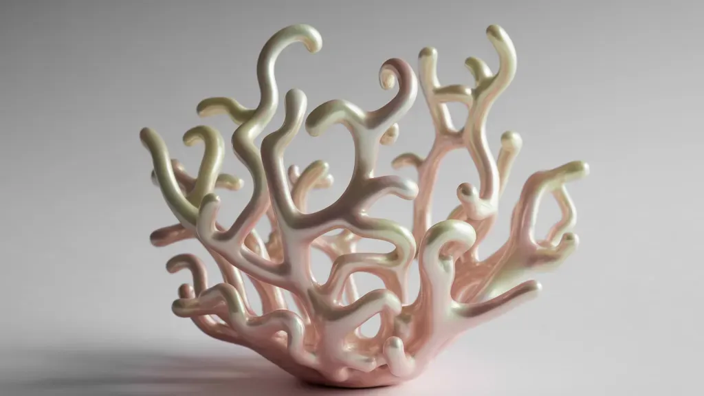
A prototype leaves the workshop as an object you can hold, push into its housing and hand to someone who has only ever seen the render. Everything between the file and that moment is a chain of small decisions. Which way up the part sits on the plate. How thick the walls really are once the slicer looks at them. Where support marks are allowed to land. Whether a hole should be drawn oversize so the shaft it was designed for actually goes in.
None of that is visible on screen. It shows up on the bench.
Rapid prototyping in Dubai usually arrives as one of two jobs: a client wants to look at a shape at full size, or a client wants to know whether two parts fit and whether one of them survives being handled. Those are different prints, and the split shapes most of what follows. We print to order, prototypes first, then exhibition pieces and art objects, and the pipeline is the same for all three with different priorities at every step.
What we do with your file before the printer sees it
Every file gets opened and checked before anything is sliced. Most models arrive in reasonable shape. A few carry problems that would print as visible defects, and a small number cannot be printed at all until the author fixes them.
What we look for:
- Closed geometry. A mesh has to describe a solid, so open shells, flipped normals and non-manifold edges get repaired or reported. Surfaces modelled with no thickness are the common version: on screen they look like a cup, and they describe nothing the printer can build.
- Scale and units. An STL carries no units, so a model exported in centimetres or inches lands in the slicer at the wrong size. A 90 mm bracket arriving as 9 mm happens often enough that we confirm one key dimension in writing before printing.
- Wall thickness. With a standard 0.4 mm nozzle, an FDM wall under roughly 0.8 mm gets dropped or printed as one fragile pass. Anything that will be picked up or screwed into wants 1.6 mm or better.
- Fine detail. Raised text, thin ribs and engraved lines below about half a millimetre vanish on FDM. On SLA they survive well, which is often the reason a part goes to resin.
- Self-intersections and duplicated coincident faces, which slice into stray blobs or hollow spots inside a wall.
Repairs that do not change the designer's intent, we do ourselves: closing gaps, fixing normals, hollowing a solid that would otherwise eat material for no reason. Anything that changes geometry goes back to the author. If a clearance is 0.05 mm and the part is FDM, we are not going to quietly decide what the fit should be.
On formats, STEP is the most useful thing to receive for a mechanical part, because exact cylinders and planes let us offset a hole cleanly instead of editing a triangle soup. STL and OBJ are fine for sculpture and display work. 3MF beats STL for one plain reason: it carries units. Preparing a model for print has its own article on this blog; here we stay with the pipeline as a whole.
An appearance prototype and a test prototype are not the same print
Before technology comes the question of what the object has to do.
An appearance prototype exists to be looked at and photographed. Orientation is chosen so the visible faces are clean and the support marks fall where nobody looks. Layers go finer, printing takes longer, and the part usually gets filled, sanded and painted. Inside it can be mostly air.
A test prototype exists to be pushed, loaded and assembled. Orientation follows the load path instead of the camera. Layer bonding is the weak direction on any FDM part, so a lug printed standing up snaps along a layer line at a fraction of the force the same lug survives when printed lying flat. Walls go thicker, perimeter count goes up, and surface finish stops mattering.
Plenty of projects need both, as two prints of the same file. Saying which one you need in the first message saves a round trip. Our gallery shows how far finished display work sits from a bare test part.
FDM or SLA: choosing the technology by what the part has to survive
FDM builds by laying down melted plastic in lines. SLA cures liquid resin layer by layer with light. The differences that matter show up on the bench, not in a spec sheet.
Size decides most jobs. FDM scales up, so large housings, body panels and display props go there: build volumes are bigger, and a big FDM part can be mostly hollow with internal ribs and still take handling. SLA tanks are smaller, and a large resin part is heavier in material and more fragile.
Then surface and detail. FDM layers are typically 0.1 to 0.3 mm tall. At 0.2 mm you see and feel the lines on a vertical wall, and on a shallow curve you see stepping where layers stack across the slope. SLA layers usually sit between 0.025 and 0.1 mm, with in-plane resolution measured in tens of microns, so a resin part reads as smooth straight off the machine. Small text and jewellery-scale detail belong to SLA.
Mechanical behaviour separates them again. FDM in a tough material takes impact, flexes a little, and can be tapped and drilled. Standard resins are harder and more brittle: a thin resin part tends to snap rather than bend, and a part left in direct sun keeps curing and can bow. Tougher resins close part of that gap, not all of it.
Speed runs on different rules too. FDM time follows part height and wall count, while SLA cures a whole layer at once, so a tank packed with small parts can be quicker per piece than the same batch on FDM. What moves a quote is material volume, machine hours, layer height, finishing work and whether the job has to be sectioned and assembled. The processes and materials we run are listed in the technologies section of the site.
3D printing tolerances and accuracy on a real part
Two numbers get confused constantly. Layer height is not accuracy. A 0.05 mm layer does not mean a 0.05 mm part.
Typical figures for the processes, not a promise on your geometry: FDM parts of moderate size usually land within a few tenths of a millimetre, commonly quoted as roughly ±0.3 to ±0.5 mm, with error growing as a share of the dimension on long parts. SLA on small parts holds tighter, in the region of ±0.1 to ±0.2 mm. Wall thickness, part length, orientation and material all move the result, which is why we say typically.
Where the error comes from:
- Shrinkage on cooling. Thermoplastic contracts as it cools, and the effect concentrates at the corners of large flat areas, which lift off the plate and pull the part out of square. Picking a lower-shrink material for a long flat part is often the whole fix.
- Resin shrinkage during and after cure. It is small, and on a long thin part it still shows as a bow.
- Circular holes on FDM print undersize, because the extrusion pushes slightly inward around the curve. A couple of tenths is normal. We either offset the hole in the file or ream it afterwards, and we say which.
- Support contact. A down-facing surface that sat on supports comes off marked, and sanding those marks removes material. When a critical face has to stay dimensional, we orient the part so that face is not down.
For fits we start from working clearances and confirm with a physical test. A sliding fit on FDM typically starts around 0.3 to 0.4 mm of gap, a press fit closer to a tenth, and on SLA those numbers roughly halve. Nobody gets an interference fit right on the first print, which is what test coupons are for: instead of printing a whole housing to learn a boss is 0.2 mm too tight, we print the 30 mm around the boss and check it in an hour.
What one iteration actually looks like
An iteration is the full loop: file in, checks and repairs, orientation and support planning, slicing, printing, cleanup, measurement, then the part in someone's hands and a list of changes.
Timing follows size and finish more than anything else. A small functional part can be printed, cleaned and measured inside a day. A large sectioned piece with paint takes considerably longer, because primer and filler dry on their own schedule and cannot be hurried by adding machines. We estimate per project instead of publishing a lead time, since a 60 mm bracket and a 2 m display piece share nothing but the word prototype.
The useful thing about version two is that the thinking is already done. Round one is where we find that the model needed hollowing, that the flange has to rotate 30 degrees to keep supports off the sealing face, that a 1 mm wall has to go to 2 mm. Round two inherits those decisions and touches only what changed, so preparation collapses to almost nothing and the print itself becomes the main remaining cost. Version two is usually faster than version one, sometimes by a wide margin.
That is also the argument for holding edits back until a physical sample exists. Designers send revised files before the first print is even off the machine, and those revisions are almost always based on the render. Once the object is on the table the change list gets shorter and cheaper to execute. Wait for the part.
Large format prototypes and printing in sections
Anything larger than the build volume is printed as sections and assembled into one object. We work from figures of a few centimetres up to constructions of fifteen metres, and past a certain size every piece is a kit.
Sectioning is a design job, not a slicer setting. Cut planes go along feature lines, panel edges and natural shadow lines where a joint disappears, rather than straight through the middle of a visible curve. Each section gets alignment geometry built in, whether dowel pockets, tongue and groove or keyed registration blocks, so the parts can only go together one way. Without it you are aligning two large curved shells by eye while the adhesive sets, which never ends well.
Joints are bonded, then filled, sanded and finished as one surface. On a display piece the seam disappears under primer and paint, which is ordinary exhibition practice rather than a trick.
Weight and structure matter more than people expect. Big printed parts are thin shells, so a tall object needs an internal frame to carry its own load and to give something to bolt to a base or a hanging point. We plan that frame alongside the section layout, with access hatches for the bolts. Joint types and assembly sequence follow the same logic on every large sectioned job we run, whatever the object.
Post-processing methods, and when to skip them
Post-processing is where a prototype becomes presentable or loses a week for nothing.
An FDM part headed for paint goes like this: supports off, seams knife-trimmed, then a coat of primer filler. The primer shows every flaw the eye missed. Then sanding, usually starting around 180 grit and working up through 320 and 400, spot filler into the low spots, primer again. A display piece goes through that cycle two or three times before colour. Sanding alone will not remove FDM layer lines, because sanding a ridge just makes a shallower ridge. You fill them, then sand the filler flat.
SLA has its own routine whatever the finish: a wash in isopropyl alcohol to clear uncured resin, a UV post-cure, supports clipped and their contact points sanded. Resin comes off the machine glossy, which hides defects until primer goes on.
When to skip all of it: fit checks, load tests and internal reviews. Primer and paint add real thickness, and on a part with a 0.1 mm clearance that is enough to kill the fit. We have stripped finished test parts for exactly that reason. If the prototype exists to answer a question about geometry, leave it raw, answer the question, and spend the finishing budget on the version you are going to show.
Send the file, say what the part has to do, and say whether it is going in front of a client or into a test rig. That last sentence changes more of the process than the file format does. Send it through the form or on WhatsApp and we will come back with a plan and a price for that specific job.
FAQ
How do I choose between FDM and SLA?
Start from size and purpose. Large parts, parts that get handled or tested, and parts that need drilling or tapping go to FDM. Small parts where fine detail is the whole point go to SLA. FDM layers typically run 0.1 to 0.3 mm, which you can see and feel; SLA runs an order of magnitude finer and comes off the machine smooth. When a project needs both qualities we split it into an FDM body with resin inserts.
What tolerances can I expect from 3D printing?
As typical process figures, FDM parts of moderate size land within a few tenths of a millimetre, often stated as roughly ±0.3 to ±0.5 mm, and SLA on small parts usually holds around ±0.1 to ±0.2 mm. Those describe the processes rather than guarantee your geometry, because size, orientation, wall thickness and material all move the result. For fits we trust a physical test coupon over a number.
Can you print an object larger than the printer?
Yes. Anything above the build volume is printed in sections and assembled into a single object, with cut lines placed where joints hide and alignment features built into every part. We work from small figures up to constructions of fifteen metres. Large pieces also need an internal frame and defined mounting points, planned together with the section layout rather than after printing.
Does a prototype need post-processing?
It depends on who will look at it. A prototype for a fit check or a load test should stay raw, because primer and paint add thickness and can destroy a tight clearance. A prototype going in front of a client gets filled, sanded and painted, usually two or three rounds of primer before colour, and that work takes real time in the schedule.
In what format should I send the file, and what if the model will not print?
STEP is best for mechanical parts, STL and OBJ are fine for sculpture and display work, and 3MF is safer than STL because it carries units. If the model has problems we say which kind: open shells, flipped normals, zero-thickness surfaces and wrong scale we usually repair ourselves, while anything that changes geometry or a clearance goes back to you. Send whatever you have, including a sketch if there is no model yet, and we will tell you what is missing before anything goes on a machine.